This section describes the firmware for the ESP32-S3, which handles motor control based on joystick input and provides a web interface for remote operation.
http.cpp/http.h: Implements the HTTP server logic for receiving control commands.joystick.cpp/joystick.h: Handles reading and interpreting input from the joystick module.main.cpp: Main program entry point. Initializes Wi-Fi, sets up the HTTP server, and coordinates motor control based on joystick input.ULN2003.cpp/ULN2003.h: Provides functions to control the 28BYJ-48 stepper motor via the ULN2003 driver board.wifi.cpp/wifi.h: Manages the Wi-Fi connection to your local network.wifi_config.h: Contains Wi-Fi SSID and password. You need to modify this file with your network credentials.
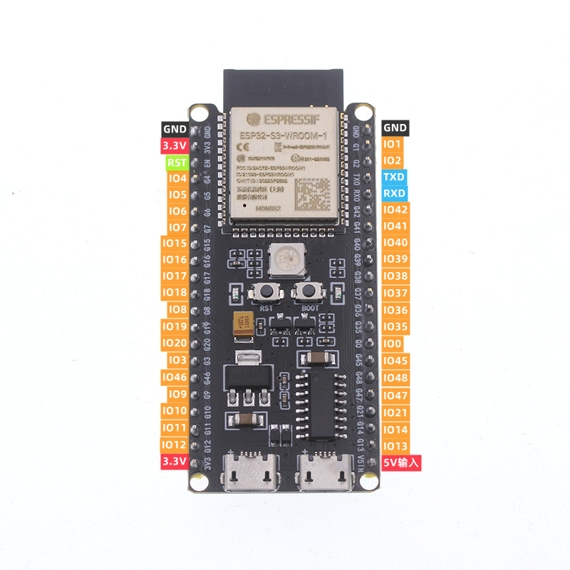
- ESP32-S3 Development Board:
- 28BYJ-48 Stepper Motor with ULN2003 Driver Board:
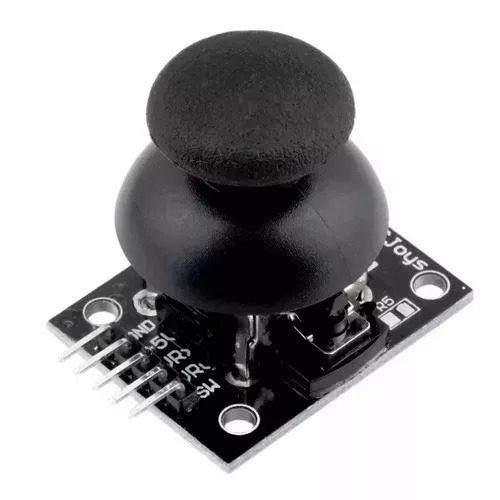
- Joystick Module:
- Power Supply Module:
-
Install the ESP-IDF Extension in VS Code:
- Follow the instructions in the "ESP-IDF Extension for VS Code Overview" to set up the ESP-IDF development environment: link
-
Obtain the Project Code:
git clone https://github.com/whiteSHADOW1234/PetCam.git cd esp_idf_esp32s3 -
Configure Wi-Fi Credentials:
You have two options for configuring the Wi-Fi credentials:
-
Option 1: Create
main/wifi_config.h:-
Create a new file named
wifi_config.hinside theesp_idf_esp32s3/maindirectory. -
Add the following content to
wifi_config.h, replacing"YOUR_WIFI_SSID"and"YOUR_WIFI_PASSWORD"with your actual Wi-Fi SSID and password:#ifndef WIFI_CONFIG_H #define WIFI_CONFIG_H #define EXAMPLE_ESP_WIFI_SSID "YOUR_WIFI_SSID" #define EXAMPLE_ESP_WIFI_PASS "YOUR_WIFI_PASSWORD" #endif
-
-
Option 2: Modify
main/wifi.cpp:- Directly edit the
esp_idf_esp32s3/main/wifi.cppfile. - Comment out or delete the line:
#include "wifi_config.h". - Modify the
EXAMPLE_ESP_WIFI_SSIDandEXAMPLE_ESP_WIFI_PASSdefinitions withinwifi.cppto your actual Wi-Fi credentials.
- Directly edit the
-
-
Set Espressif Device Target:
- In VS Code, press
Ctrl+Shift+P(orCmd+Shift+Pon macOS). - Type
ESP-IDF: Set Espressif Device Targetand press Enter. - Select
esp32s3and then choose the first option,ESP32-S3 chip (via builtin USB-JTAG).
- In VS Code, press
-
Select Serial Port:
- In VS Code, press
Ctrl+Shift+P. - Type
ESP-IDF: Select Port to Use (COM, tty, usbserial)and press Enter. - Choose the serial port that corresponds to your ESP32-S3 development board.
- In VS Code, press
-
Build, Flash, and Monitor:
- In VS Code, press
Ctrl+Shift+P. - Type
ESP-IDF: Build, Flash and Start a Monitor on your Deviceand press Enter. - This will build the firmware, flash it to your ESP32-S3, and open the serial monitor to view the output.
- In VS Code, press
-
Connect to Wi-Fi:
- The ESP32-S3 will attempt to connect to the Wi-Fi network you configured.
- The serial monitor will display the ESP32-S3's assigned IP address.
- Use the
turn right/turn leftbuttons in theserver-viewpage to send control commands to the ESP32.
28BYJ-48 Stepper Motor (with ULN2003 Driver):
- Connect the motor to the ULN2003 driver board (no special wiring needed on this connection).
- Connect the ULN2003 driver board to the ESP32-S3 and power module as shown below:
| 28BYJ-48 Motor | ULN2003 Driver Board | ESP32-S3 / Power Module |
|---|---|---|
| Red | + | 5V (Power Module) |
| Orange | IN1 | GPIO15 |
| Yellow | IN2 | GPIO16 |
| Pink | IN3 | GPIO17 |
| Blue | IN4 | GPIO18 |
| Black | - | GND (Power Module) |
Joystick Module:
| Joystick Module | ESP32-S3 |
|---|---|
| VCC | 3.3V |
| GND | GND |
| VRx | GPIO1 (ADC1_0) |
| VRy | GPIO2 (ADC1_1) |
| SW | GPIO4 |
Important
- The specific GPIO numbers used on the ESP32-S3 might vary depending on your development board. Always consult your board's pinout diagram to confirm the correct pins.
- The joystick module's VRx and VRy pins should be connected to GPIOs that support ADC (Analog-to-Digital Conversion).
The esp_idf_esp32s3/test folder contains example code for testing individual components:
joystick_motor.cpp: Demonstrates how to control the stepper motor using the joystick.
To use a test file:
- Copy the contents of the desired
.cppfile (e.g.,joystick_motor.cpp) from thetestfolder. - Paste the contents into
esp_idf_esp32s3/main/main.cpp, replacing the existing code. - Build, flash, and monitor the ESP32-S3 using the ESP-IDF extension in VS Code.
-
Missing
.hfiles: If you encounter errors about missing header files (e.g.,.hfiles), make sure that theREQUIRESsection in yourmain/CMakeLists.txtfile includes all the necessary components. You might need to add components likedriver,esp_http_server, etc., depending on the code you are using.REQUIRES driver esp_http_server ...


