Part 3: shadertoy
Now let us program a real GPU. Here is an example, how is it made?
So far I have told a lot about the general principles of computer graphics, but all the examples were made in bare C++. This time we will try GLSL. The general principle of raytracing is extremely simple. We take a camera, then we define a grid of pixels (our screen) in front of the camer, we emit a ray through each pixel, and we see where exactly it intersects with our scene. Here's an illustration:
And here is the main part of the raytracing done on a CPU: we simply loop through all the pixels and write the color into the framebuffer. Please note the #pragma omp parallel for! All the computations are independent one from another.
vec3 origin = [...];
#pragma omp parallel for
for (size_t j = 0; j<height; j++) {
for (size_t i = 0; i<width; i++) {
vec3 direction = [...];
framebuffer[i+j*width] = cast_ray(origin, direction);
}
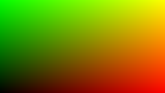
}# Step 1: fill the image with a color gradient Let us see how to do it on a GPU. The task is to fill an image with a color gradient, the idea is to be sure that we can control the output on the screen. Here is the result:
And here is the complete code that displays this image. You can see and execute this code here.
void mainImage( out vec4 fragColor, in vec2 fragCoord ) {
    vec2 uv = fragCoord/iResolution.xy;
    vec3 col = vec3(uv.x, uv.y, 0.);
    fragColor = vec4(col, 1.);
}
The main difference with the CPU code is that there is no double loop over all pixels of the picture, this is what the GPU does for us. The mainImage function is called for each pixel of the picture, it gets the coordinates of the fragCoord pixel at the input and the function must return its color fragColor. It's simple, isn't it? Check what experts can do with this approach:
This code is called a fragment shader.
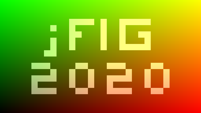
Now I want to write the conference title on top of the image, it should look like this:
The source code is available at shadertoy.
The main idea is simple. Imagine that we have a 2d array of boolean values bool jfig[32][18]. Let us split our image into a grid of 32x18 squares, and lighten those corresponding to true valies in the array jfig:
void mainImage( out vec4 fragColor, in vec2 fragCoord ) {
    vec2 uv = fragCoord/iResolution.xy;
    vec3 col = vec3(uv.x, uv.y, 0.);

    vec2 coord = fragCoord/iResolution.xy*vec2(32, 18);
    if (jfig(uint(coord.x), uint(coord.y))) {
        col += vec3(.5);
    }

    fragColor = vec4(col, 1.);
}
Of course, I do not want to store 32*18 booleans, because bool in GLSL takes.... 32 bits! Therefore I store this binary image in a bitfield jfig_bitfield and the wrapper bool jfig(in uint x, in uint y) extracts the bit we want:
#define JFIGW 32u
#define JFIGH 18u
uint[] jfig_bitfield = uint[]( 0x0u,0x0u,0x0u,0xf97800u,0x90900u,0xc91800u,0x890900u,0xf90900u,0x180u,0x0u,0x30e30e0u,0x4904900u,0x49e49e0u,0x4824820u,0x31e31e0u,0x0u,0x0u,0x0u );
bool jfig(in uint x, in uint y) {
    uint id = x + (JFIGH-1u-y)*JFIGW;
    if (id>=JFIGW*JFIGH) return false;
    return 0u != (jfig_bitfield[id/32u] & (1u << (id&31u)));
}At this step we should obtain this image:

You can see and execute the source code at shadertoy. This step is crucial, because the main raytracing job is done here. The background image we use is not a flat one, but a cube mapping texture.
Here is the source code:
struct Ray {
    vec3 origin;
    vec3 dir;
};

vec3 cast_ray(in Ray ray) {
	return texture(iChannel0, ray.dir).xyz;
}

void mainImage( out vec4 fragColor, in vec2 fragCoord ) {
    const float fov = 3.1416 / 4.;
    vec2 uv = (fragCoord/iResolution.xy*2. - 1.)*tan(fov/2.);
    uv.x *= iResolution.x/iResolution.y;
    vec3 orig = vec3(0., 0., 1.);
    vec3 dir = normalize(vec3(uv, -1));

    vec3 col = cast_ray(Ray(orig, dir));

    fragColor = vec4(col, 1.);
}
The most difficult part in this code is the first 5 lines after the declaration of the function mainImage. What is happening there? Let us suppose that the camera is placed in the origin and is directed along the -z axis. Here is an illustration, it shows the camera from the top, the y axis points towards you out of the screen:
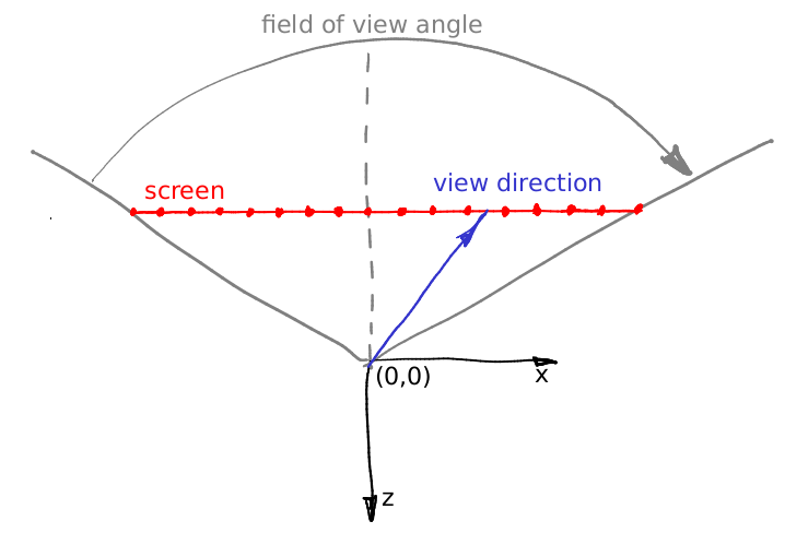
The virtual screen lies at the plane with equation z=-1. The field of view (constant) defines a sector that will be visible on our rendering. In this illustration my screen is 16 pixels wide, let us calculate its length in world units. Let us consider the triangle dfined by the red, gray and dashed grey lines. It is easy to see that tan(fov/2) = (screen width) * 0.5 / (screen - camera distance). We have put the screen at 1 meter distance from the camera, therefore (screen width) = 2 * tan (fov/2).
Now let us imagine that we want to emit a ray trough the 12th pixel of the screen, i.e. we want to calculate the coordinates of the blue vector. What is the distance from the left side of the screen to the tip of the vector? First of all, it is 12+0.5 pixels. We know that 16 pixels of the screen correspond to 2*tan(fov/2) meters. So, the tip of the blue vector is situated (12+0.5)/16 * 2*tan(fov/2) meters from the left side of the screen, or (12+0.5) * 2/16 * tan(fov/2) - tan(fov/2) meters from the intersection of the screen with the axis -z. Add to this computation the screen aspect ratio and you will get the above five lines of code. Well, in the code the camera is situated at the point (0,0,1) and the screen lies in the plane z=0, but it does not change our computations.
Как и прежде, посмотреть и запустить код этого этапа можно непосредственно на shadertoy. Примерно вот такой результат нам нужен:
Раньше наша камера была фиксирована в точке (0,0,1) и смотрела вдоль оси -z, а теперь она ездит по окружности с единичным радиусом и её взгляд прикован к началу координат. Семь новых строчек кода и коррекция двух строчек старого дают всё что нам нужно:
vec3 rotateCamera(in vec3 orig, in vec3 dir, in vec3 target) {
    vec3 zAxis = normalize(orig - target);
    vec3 xAxis = normalize(cross(vec3(0., 1., 0.), zAxis));
    vec3 yAxis = normalize(cross(zAxis, xAxis));
    mat4 transform = mat4(vec4(xAxis, 0.), vec4(yAxis, 0.), vec4(zAxis, 0.), vec4(orig, 1.));
    return (transform * vec4(dir, 0.)).xyz;
}

void mainImage( out vec4 fragColor, in vec2 fragCoord ) {
[...]
    vec3 orig = vec3(-sin(iTime/4.), 0., cos(iTime/4.));
    vec3 dir = normalize(vec3(uv, -1));
    dir = rotateCamera(orig, dir, vec3(0.));
[...]
}Теперь давайте нарисуем квадратик с длиной ребра полметра, живущий на плоскости z=0:
Для этого нам достаточно добавить совсем немного кода в функцию cast_ray():
vec3 cast_ray(in Ray ray) {
    if (abs(ray.dir.z)>1e-5) {
        float dist = (0. - ray.origin.z) / ray.dir.z;
        if (dist > 0.) {
	        vec3 point = ray.origin + ray.dir*dist;
        	if (point.x>-.25 && point.x<.25 && point.y>-.25 && point.y<.25) {
                      return vec3(0.2, 0.7, 0.8);
        	}
          }
    }
   return texture(iChannel0, ray.dir).xyz;
}
Посмотреть и запустить код этого этапа можно непосредственно на shadertoy.
Как это работает? Для начала нам нужно найти точку пересечения луча и плоскости, в которой живёт квадратик (z=0). Я проверяю, не параллелен ли луч плоскости if (abs(ray.dir.z)>1e-5). Уравнение луча выглядит следующим образом: vec3 point = ray.origin + dist*ray.dir, где dist - это расстояние от текущей точки луча до начала, правильно? Нам известна координата z точки пересечения (z=0); тогда расстояние от начала луча до точки пересечения считается как float dist = (0. - ray.origin.z) / ray.dir.z. Ну а дальше дело техники, получив точку пересчения point мы проверяем, укладываются ли координаты x и y в квадрат со стороной полметра с центром в начале координат. Вуаля!
Ну раз уж мы умеем нарисовать один квадрат, нам совсем несложно нарисовать шесть квадратов, которые составляют куб! Посмотреть и запустить код этого этапа можно непосредственно на shadertoy.

Вот так выглядит код пересечения произвольного луча с кубом, ориентированным по осям системы координат:
struct Box {
    vec3 center;
    vec3 halfsize;
};

bool box_ray_intersect(in Box box, in Ray ray, out vec3 point, out vec3 normal) {
	for (int d=0; d<3; d++) {
    	if (abs(ray.dir[d])<1e-5) continue;
		float side = (ray.dir[d] > 0. ? -1.0 : 1.0);
        float dist = (box.center[d] + side*box.halfsize[d] - ray.origin[d]) / ray.dir[d];
		if (dist < 0.) continue;
        point = ray.origin + ray.dir*dist;
        int i1 = (d+1)%3;
        int i2 = (d+2)%3;
        if (point[i1]>box.center[i1]-box.halfsize[i1] && point[i1]<box.center[i1]+box.halfsize[i1] &&
        	point[i2]>box.center[i2]-box.halfsize[i2] && point[i2]<box.center[i2]+box.halfsize[i2]) {
            normal = vec3(0);
            normal[d] = side;
            return true;
        }
	}
    return false;
}А теперь давайте добавим диффузное освещение (flat shading), мы же шейдеры рисуем :)
Посмотреть и запустить код этого этапа можно непосредственно на shadertoy. Вот так выглядит наша функция шейдинга:
struct Light {
    vec3 position;
    vec3 color;
};

Light[] lights = Light[]( Light(vec3(-15,10,10), vec3(1,1,1)) );

vec3 cast_ray(in Ray ray) {
    vec3 p, n;
    if (box_ray_intersect(Box(vec3(0.), vec3(.25)), ray, p, n)) {
	   	vec3 diffuse_light = vec3(0.);
    	for (int i=0; i<lights.length(); i++) {
       		vec3 light_dir = normalize(lights[i].position - p);
	       	diffuse_light  += lights[i].color * max(0., dot(light_dir, n));
        }
       	return vec3(0.2, 0.7, 0.8)*(vec3(.7,.7,.7) + diffuse_light);
    }
	return texture(iChannel0, ray.dir).xyz;
}Раз уж мы умеем рисовать один куб, то нарисовать несколько не должно составить труда:

Посмотреть и запустить код этого этапа можно непосредственно на shadertoy. Ровно как и в случае с логотипом (двумерной картинкой), я определяю кролика как трёхмерный массив булевых значений, упакованный в битовое поле:
#define BUNW 6
#define BUNH 6
#define BUND 4
#define BUNVOXSIZE 0.1
uint[] bunny_bitfield = uint[]( 0xc30d0418u, 0x37dff3e0u, 0x7df71e0cu, 0x004183c3u, 0x00000400u );
bool bunny(in int cubeID) {
    if (cubeID<0 || cubeID>=BUNW*BUNH*BUND) return false;
    return 0u != (bunny_bitfield[cubeID/32] & (1u << (cubeID&31)));
}
Если вам не очень наглядны константы типа 0xc30d0418u, то вот так они выглядят в человекочитаемом варианте :)

Ну а дальше пишем функцию пересечения луча и вокселизированного кролика:
bool bunny_ray_intersect(in Ray ray, out vec3 point, out vec3 normal) {
    float bunny_dist = 1e10;
    for (int i=0; i<BUNW; i++) {
    	for (int j=0; j<BUNH; j++) {
    		for (int k=0; k<BUND; k++) {
                int cellID = i+j*BUNW+k*BUNW*BUNH;
				if (!bunny(cellID)) continue;
                Box box = Box(vec3(i-BUNW/2,j-BUNH/2,-k+BUND/2)*BUNVOXSIZE+vec3(.5,.5,-.5)*BUNVOXSIZE, vec3(1.,1.,1.)*BUNVOXSIZE*.45);
                vec3 p, n;
                if (box_ray_intersect(box, ray, p, n) && length(p-ray.origin) < bunny_dist) {
                    bunny_dist = length(p-ray.origin);
                    point = p;
                    normal = n;
                }
    		}
    	}
    }
	return bunny_dist < 1e3;
}
И в функции cast_ray() заменяем вызов box_ray_intersect() на bunny_ray_intersect(). Вот и кролик!
Ну и самая последняя вещь - это раскрасить кубики в разные цвета. Посмотреть и запустить код этого этапа можно непосредственно на shadertoy.
Тут я велосипед не стал изобретать, и честно стянул чужой код, который для данного целого числа (номер кубика) даёт цвет:

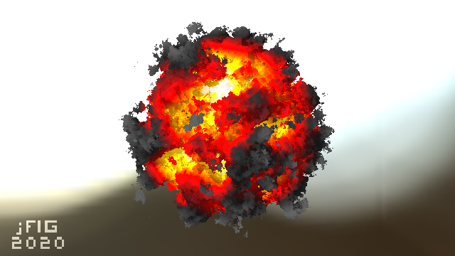
# Всё, наш шейдер готов! Shadertoy.com полон крайне интересных шейдеров, но зачастую понять, как они устроены, могут только эксперты. Если вам интересна эта тема, можете [попробовать разобрать](https://github.com/ssloy/tinykaboom/wiki) мой мультяшный взрыв (кликабельно):
Напоминаю, что если вы говорите по-французски или живёте во Франции, то вы можете претендовать на приз (RTX Quadro) в нашем конкурсе jFIG2020. Правила конкурса будут опубликованы в начале недели, но в целом достаточно мне прислать ссылку на ваш шейдер, а так же на как можно более подробное описание того, как он работает.
Если же вы не живёте во Франции и не говорите по-французски, то хоть на физический приз вы претендовать и не сможете, но вы можете участвовать во всей этой движухе на внеконкурсной основе, нашу нематериальную благодарность и всемирную славу обеспечим :)
Да и вообще пофиг призы, самое главное расцвечивать пиксели!