REMDx is a board that is able to measure 0-35V DC voltage with a resolution of 1mV, 0-8A DC current with a resolution of 250uA (which can be changed by replacing the shunt resistor), burden voltage, and power. Furthermore, all measurements can be performed over two channels.
The REMDx (Realtime Efficiency Measurement Unit x) was originally intended to measure the efficiency of Switch Mode Power Supplies / Linear Regulator hence the name REMDx but later evolved into a datalogging device. See the schematic of REMDx (Github repo).
Below you can see the REMDx PCB board.
 The system block diagram of the REMDx is shown below.

The REMDx is capable of measuring:
- 2 channel voltage measurement 0-35V with resolution of approximately 1mV
- 2 channel current measurement 0-8A with resolution of approximately 250uA, coms with 10mOhm shunt resistor.
- 2 channel power measurement
- 2 channel burden voltage measurement
- 4 Digital input pins max. 3.3V (INTx - interrupt pins)
- 2 Analog input pins max 3.3V (MCU ADC with 12bit)
- 2 Digital output pins with selectable output voltage levels (3.3V, 5V, and 12V)
- 2 PWM pins with selectable output voltage levels (3.3V, 5V, and 12V)
Micro-SDcard slot for saving stream data (stream data is serial data from USB). The current firmware does not have this functionality, however, it will be added soon.
The OLED display (ssd1306) displays the bus voltages (Vbusx), currents (Isensx), burden voltages (Vburdx), and powers (Powerx) for both channels. On the first row of the OLED display, the ambient temperature and efficiency are also shown. The OLED display data layout is shown in the figure below.

Data stream capability using USB for datalogging and visualization with Python (see scripting folder)
- Download and install STM32CubeProgrammer

- Connect REMDx to your PC with a USB cable that is capable of data transfer.
- On REMDx press and hold the BOOT button, then press the RESET button and let go of both buttons. This will put REMDx in programming mode.
- Open STM32CubeProgrammer select USB (Blue dropdown menu on the right column), then click the refresh icon until "USB1" shows up on port (Serial number 2081325A4146), then click connect.

- Download FW.elf file to your PC. Go back to STM32CubeProgrammer press "open file" then press download. Now REMDx should be programmed or updated to the newest firmware.


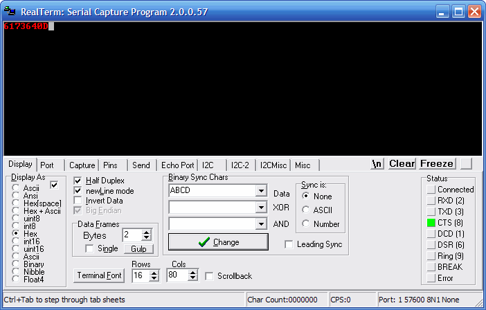
- Download and install Realterm or similar terminal program.
- Select the COMPORT, find it under Device Manager in Windows

- Select the BAUD RATE 115200 and connect, now you should see a continuous data stream as shown in the picture below.


REMDx can be configured using register map, and the configuration can be saved in EEPROM (default configuration can be restored).
COMMUNICATION PROTOCOL
The REMDx should be written as follows:
- A check command "* L #" of 5 bytes ("" are not part of the command) is sent to the device as numbers. Where L is the length of the command sent next (L is always 5).
- To write to or read from the device, a second command of 5 bytes in ASCII is sent.

The second command is referred to as "the command" from this point on.
- Byte 1: Indicate the command to read or write
- Bytes 2 and 3: Specify the register you are writing to or reading from (32 registers are available for read or write operation).
- Bytes 4 and 5: Specify the data you are writing to the device. When reading from a register, ignore these two bytes and set them to 0.
To indicate register data to and from the device, hexadecimal numbers are utilized.
Use the letter "w" as the initial character of the command you are sending to the device if you want to write to a specific register.
Connect REMDx to your PC and open RealTerm.
To stop stream data from REMDx, set the meas_mode bit to 0, see register map
Stop stream data.
w0304Writing 0x07 to register 2.
w0207w - to specify a write command
02 - register number 2 as hex value
07 - data written to register 2 as a hex value.
Relating to the register map:
set_led1=1
set_led2=1
As a result of this command, the onboard LEDs should turn on
Use the letter "r" as the initial character of the command you are sending to the device if you want to read from a specific register.
Reading the content of register 2.
r0200r - to specify a read command
02 - register number 2 as hex value
00 - Not important when reading a register.
Outcome of RealTerm

Python scripting also allows for the reconfiguration of REMDx and live data visualization.
Here is some sample code to turn on led1 and led2.
from datacontrol import dataCTRLMaster
from plotcontrol import plotMaster
remd = dataCTRLMaster()

# LED Example
print(f"set_led1 = {remd.set_led1}")
remd.set_led1 = 1
print(f"set_led1 = {remd.set_led1}")
print(f"set_led2 = {remd.set_led2}")
remd.set_led2 = 1
print(f"set_led2 = {remd.set_led2}")
Example code for live plot of bus voltage of channel1.
from datacontrol import dataCTRLMaster
from plotcontrol import plotMaster
remd = dataCTRLMaster()

# Example - Live plot of the bus voltage of channel 1
plotter.plotData(1)
