This repository contains the code of the DIY Spectroscope, which uses a camera and an analogue (pocket) spectroscope to measure the spectrum of (visible) light.
Check out the video of this project for instructions on how to use it. Note, unlike in the video, the GUI is now made up of just one program, which contains the calibration tabs and the tab showing the spectrum.
The optimization is done via an additional python script (without a GUI). The additional optimization step is not essential, you may get results that are good enough for your purpose, even without additional optimization.
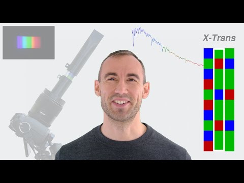
Note, currently the code is only implemented for cameras with whose colour filter array uses the X-Trans pattern (Fuji cameras).
I use pyenv, which is a program that allows you to run multiple versions of python on your computer. I've written the code for this project for python version 3.12.2. If this version is not installed in your pyenv then you can install it with pyenv install 3.12.2 (the code may also work with other versions but I haven't tested that).
Next we're going to create a virtual environment (using pyenv-virtualenv) that makes use of the newly installed python version. Run pyenv virtualenv 3.12.2 Spectroscope to create a virtual environment called Spectroscope which uses python version 3.12.2.
With pyenv versions you can see all available versions. The one that's used inside of your current folder is marked with an asterisk (*). To select the new virtual environment we create a new file with echo Spectroscope > .python-version. If you run pyenv versions again then the virtual environment Spectroscope should now be active (in the current and all of it's subfolders, unless overwritten by another .python-version file).
Make sure that exiv2, boost and gphoto2 are installed on your system. On Arch Linux they can be installed with sudo pacman -S exiv2 boost gphoto2.
For the optimization I'm using the machine learning framework JAX. Since I'm using an NVIDIA GPU I installed JAX with pip install -U "jax[cuda12]". For a CPU only installation or other devices check out JAX's installation instructions.
Now we can install the required python packages with pip install -r requirements.txt (you may have to use pip3 on some OSs). I've split the code of the main program and that of the optimization of the response functions into two separate directories (code and code_optimization). You'll have to install the requirements.txt file in both folders. If you don't want to do the optimization then you don't have to install JAX and the requirements file in the code_optimization folder.
This section only describes the actual usage of the code. For information about which lens to choose, which settings to use, how to take pictures, etc. check out the video.
The code is split up into two parts. The main program covers everything we need for using the program and a part of the calibration process. The optimization code is only used during calibration.
To start the program navigate into the code directory and run python main.py. This opens the main window. On top there are a few options for loading and saving settings files and loading pictures. Below that there are seven tabs:
- Picture
- Single Wavelength
- Wavelength-Pixel Mapping
- Wavelength Interpolation
- Spectral Response
- Response Mixing
- Spectrum
This section gives a brief overview of how to calibrate the setup. Note, most of what's described here is shown in the video. We'll need at least two pictures, one of the sky and one of a reference lamp (with a known colour temperature).
I tried to touch the setup as little as possible between taking those pictures because for the calibration it's important that the image of the spectrogram is in exactly the same place on those two pictures.
- Open the program and save a new settings file.
- Take a picture of the spectrum of the sky and load it into the program.
- Get the black levels from the exiv data of the image and enter them in the Black Levels section in the sidebar (under General).
- You can put the same black levels into the Black Levels section under This Tab. However, the image is usually easier to look at if you enter a larger value in this section.
- Make sure the white rectangle (tab Picture) covers the entire spectrogram.
- In tab Single Wavelength find the y-coordinate range where the signal is relatively constant.
- Back in tab Picture set Top and Bottom in the sidebar to the range found in the previous step.
- In tab Wavelength-Pixel Mapping the thick lines show the mean of the y-coordinate range we chose before. The thin lines show the 90% confidence interval. Make sure the thin lines are close to the thick lines (otherwise we don't have a reliable signal).
- Still on tab 3, find the x-coordinates where the signal becomes very small.
- Update the Left and Right values in the Picture tab with these coordinates so that only the range with a signal is covered.
- If you took a picture of the sky, in tab 3 you should now see the locations of some of the spectral lines (dips in the red, green and blue lines). Check out the spectrum of the sun. You should be able to easily identify some of the major spectral lines. Their nanometer values are already entered in the sidebar of tab 3. You now have to enter the corresponding x-coordinates in the image.
- In tab Wavelength Interpolation, the orange dashed line is a linear fit through the data points we've just mapped. The calibration points should be on or very close to that line.
- Now load an image of the spectrogram of a halogen lamp. The spectrogram should be in the same place on the image as in the first picture (check the variation in tab 3, you may have to adjust the y-coordinate range in tab 1 -- the Cos^4 effect depends on the light that came in).
- In tab Spectral Response, in the sidebar, add the color temperature of the lamp you've just loaded.
- Lamps usually block out UV-light. Find the nm-coordinate where your red, green and blue signals rapidly fall to zero. Cut the spectrum there by updating Lower Cutoff in the sidebar.
- Visualize the response functions by enabling the checkboxes under Show in Plot. Make sure everything looks alright.
- Update the name under Save Response Functions press Save.
- In tab Response Mixing, in section Function Details, press plot to visualize the response functions and press use to use them.
- You can add multiple response functions. If you use multiple response functions then their average will be computed (you can set the range where each of the signals should be used below where it says Fade In/Out). This can be useful when taking multiple pictures of the same lamp, for averaging out noisy data.
- Small values or steep slopes in the response function can lead to inaccuracies. Under Channel Mixing enter the nm-ranges where each of the three colours is not too small and not too steep. The blue and green ranges should overlap in some part of the spectrum. Same for the green and red ranges.
- In tab Spectrum you should now see the estimated spectrum of the lamp you've used for calibration. This should be very accurate (because we used this lamp to compute the response functions).
- Load a different image, e.g. the image of the sky we used before. The spectrum predicted by the three colours should still be relatively consistent. It may not be perfectly consistent though. In that case, you may want to adapt your response functions by following the optimization procedure described below. Otherwise you can skip the next section and go straight to After the Calibration.
The optimization process replaces the response functions we computed above with a simple neural network (three multilayer-perceptrons).
Initially, for the reference lamp(s), I used the exact colour temperature that's written on the packaging. However, these colour temperatures are usually rounded to the closest 100K so we don't know the exact value. To try and improve that a little I made the colour temperature a learnable parameter. So for each lamp the model will try to learn the colour temperature that is most consistent with all the other data. However, since we know that the colour temperature should be within 50K of the temperature written on the packaging, I also restrict the learned colour temperature to be close to that temperature.
The loss function to be minimized has four components:
- The spectrum predicted by all three colours should be identical in the regions where the response functions overlap. The first part of the loss minimizes the difference between the predicted spectra.
- The spectrum predicted for the reference lamp(s) should match the spectrum of a black body of the learned colour temperature. The second part of the loss minimizes the difference between the predicted and target spectra.
- The response functions shouldn't be extremely steep (it's unlikely that there are jumps in the response functions). The third component of the loss penalizes very steep slopes.
- The learned colour temperatures should be close to the colour temperatures written on the packaging. The fourth component of the loss function penalizes the difference between the two.
I added the third component of the loss function as a test at some point and never removed it. Right now I'm not certain if it's actually required. I should probably test that at some point ...
The data used in the optimization process should be saved in folder code_optimization/sources. First we need to export some data from the main program.
- In tab Response Mixing export the Combined Response Function and the Component Weights (in section Export Data). Save the combined response function as sources/crf.npy and the weights as sources/weights.npy.
- In the sources folder create a subfolder called ref. Inside that folder:
- Create a file called lamps.txt. Inside the file, create one line for each lamp. Each line contains four columns. The first is the name of the lamp, the second the colour temperature on the packaging. The third and fourth give the nanometer range where the spectrum of the lamp should be used. Below is an example of the file showing the two lamps that I used.
- Load the image of the spectrogram of each lamp that you're going to use into the main program. In tab Wavelength-Pixel Mapping, in section Export Data, press Signal. Save the file as ref/{description}_signal.npy (replace {description} with something appropriate). You can export multiple images of the same lamp using different descriptions.
- For each image you've exported create a file ref/{description}_color-temperature.txt. That file should only include the name of the lamp that this image refers to (i.e. the name that you created in step 1 in lamps.txt).
- In the sources folder create a subfolder called sky. That folder will hold the data of many images of the sky, which are used for the first component of the loss function. You can use the interval timer shooting functions on your camera. Ideally you take these pictures on a day where the light changes a lot, e.g. on a day with a few clouds that move quickly, because we want to have a lot of variation in the data. A uniformly grey sky is not suitable because it will give little variation in the data.
- Save the raw images of the spectrograms of the sky in some folder (not in the sky folder we created above). Make sure nothing else is saved in that folder.
- Load one of the images into the program and make sure that the wavelength-pixel mapping is correct and that the y-coordinate range is appropriate.
- Then, still in tab Wavelength-Pixel Mapping, under Export Data press Signal of Files in Folder. As input select the folder where the raw images are saved. As output select they sky folder we created above. This will extract the signal of each file in the source folder and save it in folder sources/sky.
Sample folder structure of code_optimization/sources:
sources/
crf.npy
weights.npy
ref/
lamps.txt
2500K_1_color-temperature.txt
2500K_1_signal.npy
2500K_2_color-temperature.txt
2500K_2_signal.npy
...
2700K_1_color-temperature.txt
2700K_1_signal.npy
...
sky/
DSCF0001.npy
DSCF0002.npy
...
Sample of lamps.txt
E14_2500K 2500 425 700
E14_2700K 2700 524 700
The output of the optimization process will be saved in folder code_optimization/outputs. Create that folder if it doesn't exist.
In file settings.yaml you can adjust the training settings to your needs. Most of the settings should be self-explanatory but it's probably worth looking at the code to understand what some of them do. I'm just highlighting one called exclude_nm_ranges which is a subsection of main_training. In the main program under Response Mixing - Channel Mixing we set the ranges where each colour should be used. This setting allows you to further exclude certain nanometer-ranges. I included it because the red response function has a small but constant value in a large part of the spectrum. So I want to use as much of it as possible. However, there's also a very steep part of the red response function in middle that I want to exclude.
You may also want to look at setting loss_fn_weights in main_training - training. This setting determines how much weight each of the four components of the loss function gets.
For the actual optimization, in the command line, navigate to folder code_optimization and run python train_initial_guess.py. This will create the parameters for the network and it will pre-train them so that the output is similar to the response functions we found before. They don't have to match perfectly, this is just an initialization. Then, for the main training process run python train.py. This may take a while, depending on your hardware and the number of epochs you set in the source file (I picked quite a large number of 500k, which is probably not necessary for this relatively simple problem).
When the main training process has finished then there should be three new files in the outputs directory. One will contain the colour temperatures that the model found for the lamps. If they look unreasonable try to adjust the weights in the settings file. For example, if the predicted colour temperatures are 2200K for a 2500K lamp then increase the weight of the fourth component of the loss function. Obviously this is not a perfect way of estimating the colour temperature of lamps but in my case the colour temperature of the 2700K was stable at around 2699K, even at smaller weights. So I'm decently confident in the result.
To be able to use the response functions in our program we have to import them. In the main program go to tab Response Mixing. In section Function Details press Import and select the trained response function in the output folder of the optimization process. Then press use on the imported response function and disable all other response functions that were previously used.
Once you've calibrated your system it should be quite easy to use it.
- Load a new image of a spectrogram.
- In tab 3 make sure the variation of the signal is small. If it's not then adjust the y-coordinate range.
- If you took an image of the sky, in tab 3 make sure that the spectral lines are still in the right place. They can change if the way you mount your spectroscope to the lens is not very stable. If they have changed then adjust your wavelength-pixel mapping.
- In tab 7 you should now see the spectrogram.
If and when I've got time I may do the following improvements (this is not an exhaustive list):
- Support Bayer pattern
- Apply Cos^4 correction to spectrogram so we don't have to manually pick a y-coordinate range (as described in step 6 in Calibration Steps)