Wiring
Ideally you can put some small connectors on the ESC and on the motor wires.
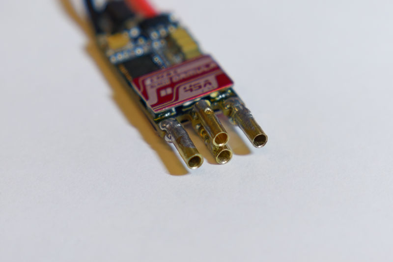
Two connectors needs to be put on the center common-shared phase. The two side phases only need one connector each.

To deliver the full voltage to the motors, they have to be wired in the correct orientation, so it is important to be able to reconnect a motor if it is connected backwards by mistake.
If the behavior is not correct, then the phasemap can be changed through the CLI. The command is phasemap <num> where <num> should be a number that is 1 or 2 or 3. For example, phasemap 1. Change it until it works.
(refer to the page on configuration, and the guide of finding the phasemap value)
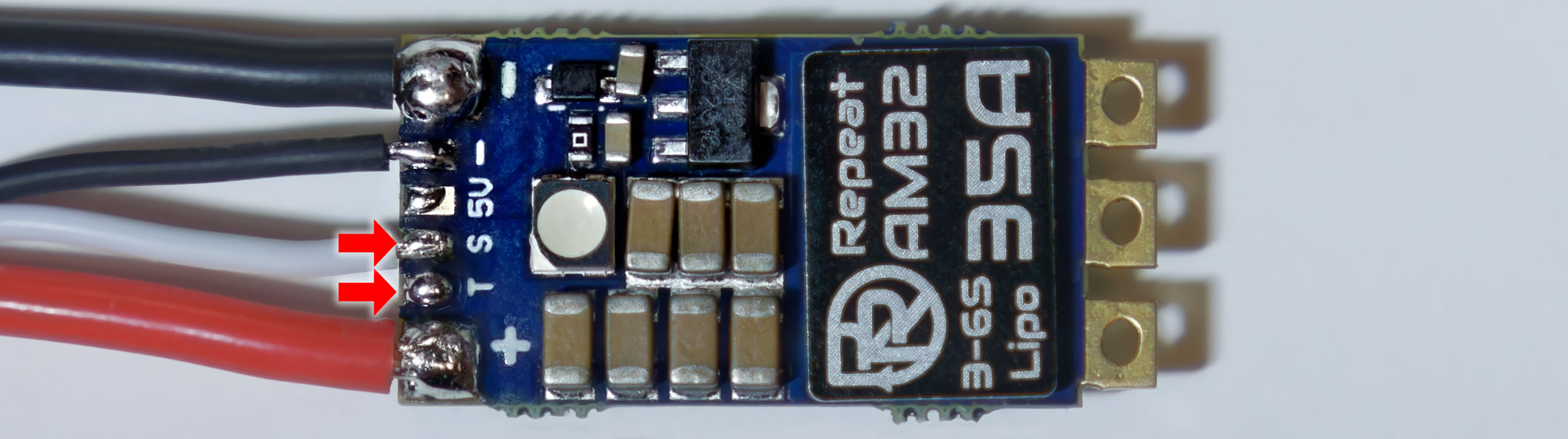
The telemetry signal, if it exists, is typically very close to the main signal input. It might be labelled with a T or with a word that starts with T.
note: Hydra firmware does not ever actually provide telemetry, this functionality simply does not exist and I do not plan on adding it.
The SWD signals are called SWDIO and SWCLK. These either appear as a pair or in a group of 4. If you are using one of the ESCs that is officially supported, you should not need to look for these. But there is a guide on finding these pads here
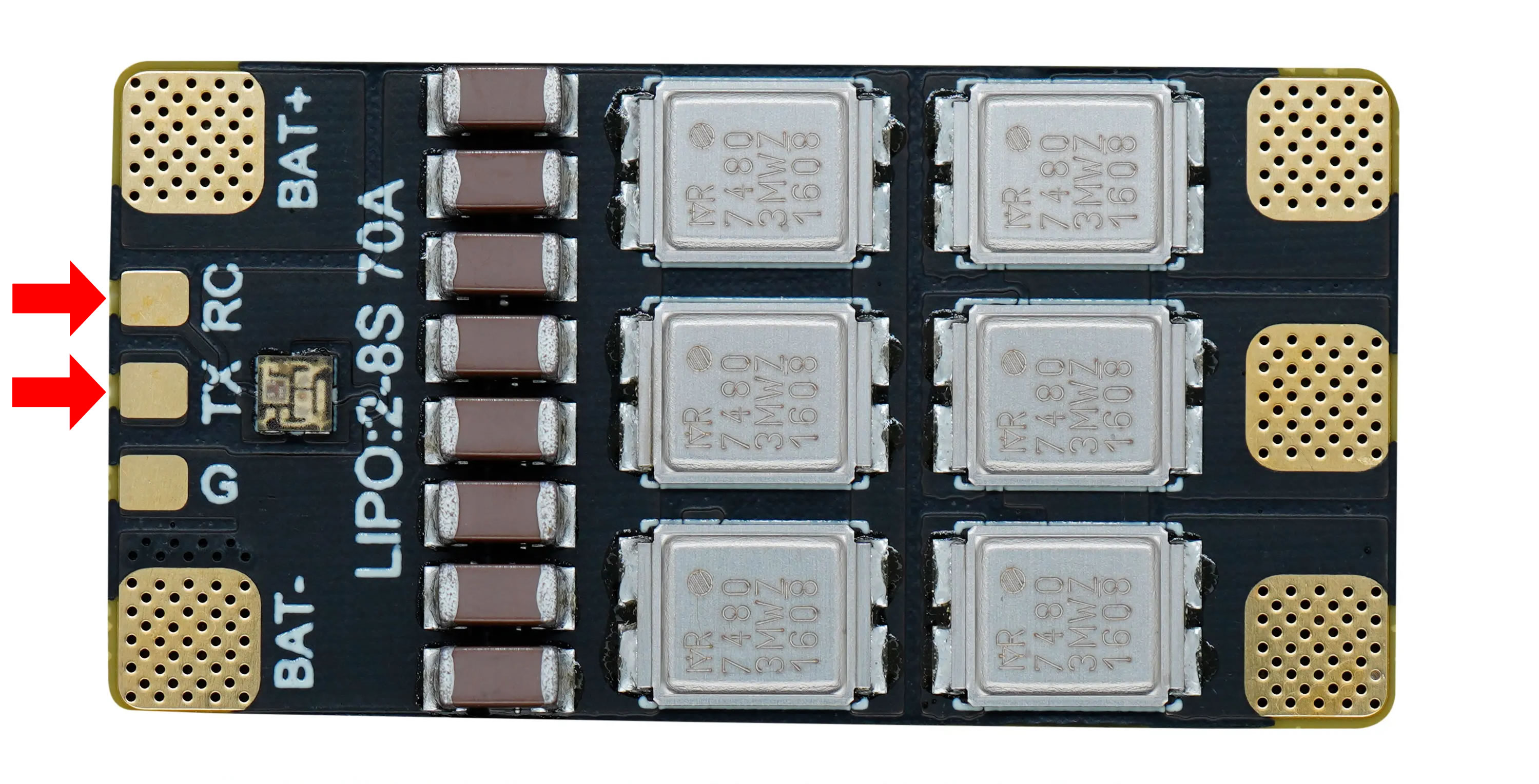
The first channel input will always be the main input signal. That usually means the signal wire that came pre-soldered with the ESC, or the traditional signal input solder-pad on the ESC (there might be a S letter beside it, or RC).
For the second channel input, ideally there is a telemetry solder-pad that can be used.

If there is no telemetry solder-pad, then use the SWCLK pad. (you can short SWDIO to SWCLK if you are unsure which one is which)
If there is a telemetry pad, then use it for the CRSF signal

If the telemetry signal is missing, and the ESC is using GPIO PA2 as the main signal input, then the CRSF input is the main signal input. Connect it to your receiver's CRSF output (TX) signal.

If there is no telemetry solder-pad and the ESC is not using GPIO PA2 as the main signal input, then use the SWCLK pad. (you can short SWDIO to SWCLK if you are unsure which one is which)
The command in CLI is inputmode <num> where <num> is a number. For example, the command will look like inputmode 1 to change the input mode to be CRSF.
Here's a table of modes and their numbers:
| MODE | NUM |
|---|---|
| RC PWM Pulse | 0 |
| CRSF | 1 |
| RC using SWCLK | 2 |
| CRSF using SWCLK | 3 |
(refer to the page on configuration)