Soldering and assembling
The 5.1 preamplifier board uses both surface-mounted and through-hole type components. To minimize soldering difficulties, we recommended soldering all the SMD components at the beginning.
The most recommended soldering order lists in below:
- PIC16F886 MCU (U4)
- TL074 and TL072 operational amplifier ICs (U6, U7, U8, and U9)
- All SMD resistors and ceramic capacitors
- SMD electrolytic capacitors
- Three ground isolation jumpers (R1, R2, and R3)
- All through-hole type resistors
- SMD trimpot (RV1)
- Mylar capacitors
- JST connectors and pin headers
- PT2258 IC or 20-pin IC socket (U5)
- LM317, LM337, and uA7805 regulators with heatsink (U1, U2, and U3)
- Through-hole type Electrolytic capacitors
- Transformer cables (J1)
- Audio input and output cables
In our prototype, we use a custom heatsink for all the voltage regulators. The recommended heatsink (front) layout is as follows:
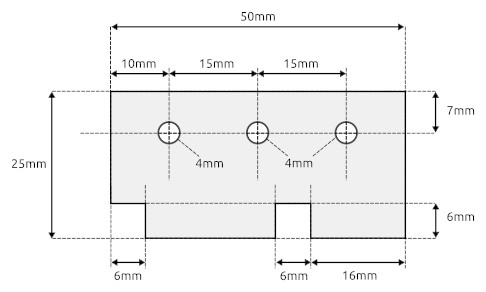
To construct this heatsink, we use a generally available 2.5mm, flat Aluminum bar.