Home
This Wiki shows all the relevant information about updating the Pioneer 2Dx from its factory construction to the system used by the SwarmUS team.
The SwarmUS team was tasked to update old robots that was not longer used by the client's lab and to use them has a test bench to test the system developed by the team. Since the Pioneer electronics and software were obsolete, only the chassis and the motor were kept and a new electrical and software architecture were designed.
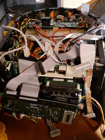
The first step is to removed all the internal electronics and battery keeping only the chassis and the motors:
With all the electronics removed, a simpler architecture was implemented. The main goal of the electrical design was to regulate and distribute power to all the needed sensors of the robot, to the main computer which is a Raspberry Pi 4, to the motors and to the HiveBoard and BeeBoard designed by the team. The sensors include a A2M8 RPLidar for mapping and obstacle detection and a D400 series Realsense camera. The circuit diagram is shown below:
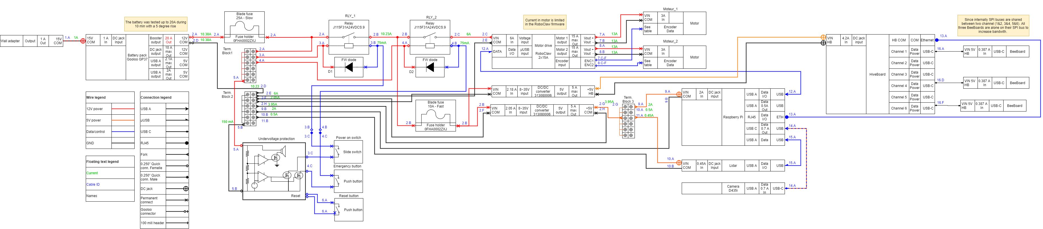
The model of the motors used in the Pioneer 2Dx is GM9236S019-R1. Their reference voltage is 12V and and their stall current 16.9A. However, the firmware of the motor driver was adjusted to limit 12.5 per motor and the motor acceleration is limited by ROS to 0.6m/s^2 . Since the motors have quadrature encoders, the drive that has been selected to read directly the encoders. All the requirements lead to chose the RoboClaw 2x30A Motor Controller. The [RoboClaw 2x15A Motor Controller](RoboClaw 2x15A Motor Controller (basicmicro.com)) could have been an adequate choice with the current limitation but components shortage force used to buy the more powerful one.
Before using the Roboclaw, it must be configured. To do this, follow the instructions on the page Roboclaw setup.
There is 3 power rails available in the designed system:
- 1x Non regulated 12V from the battery
- The 12V is used by the relays' coil and by the motor driver.
- Can support up to 20A (which was the maximum at which it was tested)
- 2x regulated 5V bus from regulators
- One bus for the Raspberry Pi4 and the sensors and the other for the HiveBoard and BeeBoards