Installation on Mega Drive 2
This diagram covers at least the following logic board revisions:
- PC BD MD2 VA1 PAL
- PC BD MD2 VA1.0 PAL
IMPORTANT NOTE: The +5V and GND points in the diagram below are swapped!

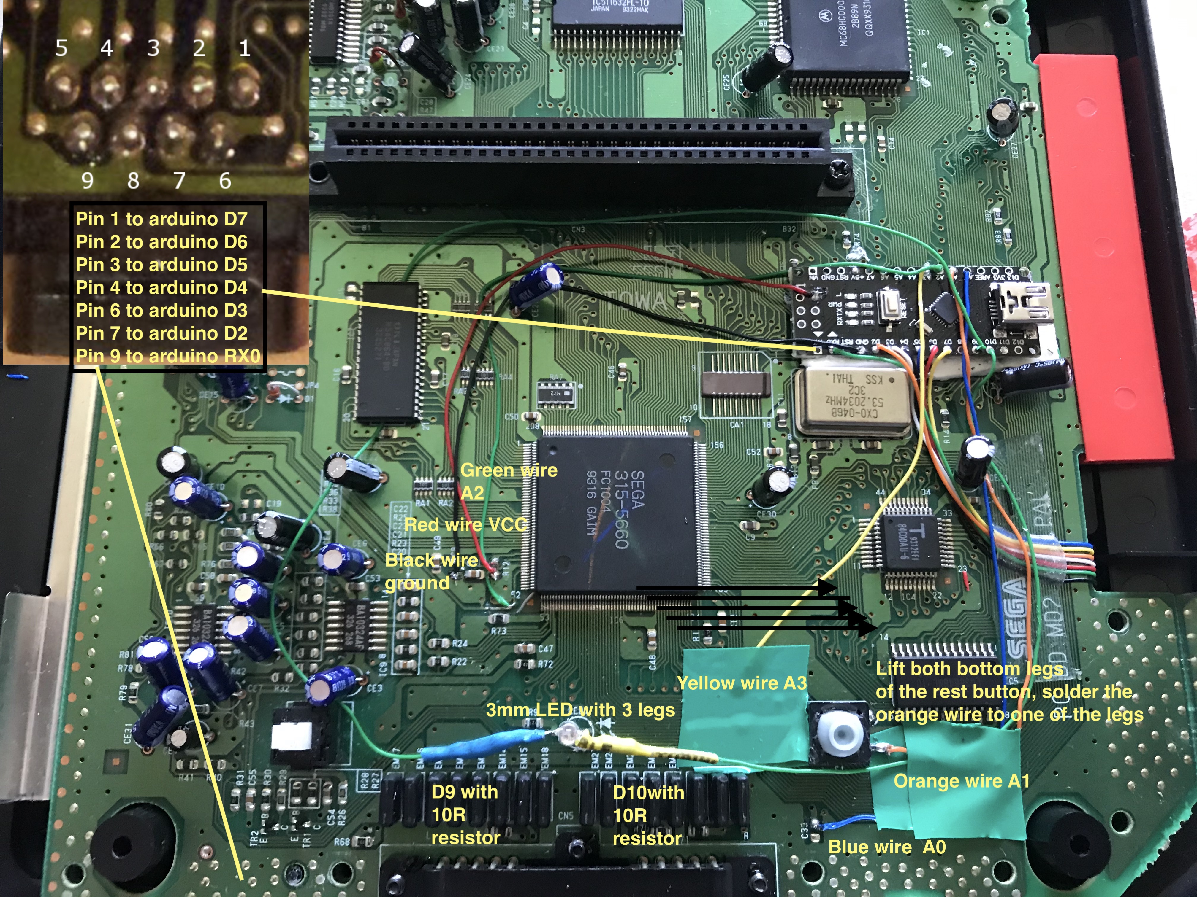
A few notes about the Reset Button/Orange point:
- You need to lift both legs from the PCB.
- Actually, you are recommended to desolder the whole reset button, lift the bottom legs and resolder the top legs.
- You only need to solder one of the bottom legs to the chip. Any one will do, choose the one that better fits your intended wire routing scheme.
- Before resoldering, apply some heat shrinking tube (or insulation tape) to the lifted legs, to ensure that they won't touch the PCB anymore.
If you want to replace the LED with a new one, you can connect its cathode to the left contact of the old one: it is connected to ground through a 120 Ohm resistor, so if you're using a single led you can just connect the anode straight to your chip. If you are using a dual or RGB led instead, you should put a small value resistor (10-47R maybe, the bigger, the fainter your colors will be) in series with every anode. Also, I am not sure a 5 mm led will fit, so I recommend sticking to 3 mm LEDs.
Following is an example installation by AssemblerGames forum user nextria: