-
-
Notifications
You must be signed in to change notification settings - Fork 30
Installation
Installation involves a few steps:
-
First of all, you need to get an Arduino Nano and flash it with the firmware. You can do this yourself following the instructions or ask someone else with some knowledge of the Arduino platform to do it for you.
-
Open up your Mega Drive/Genesis and identify the logic board model: look at what is printed on it and get the diagram for your model below:
If your model is not listed, please open an issue providing high resolution photos of both sides of your logic board, and we will try to help.
Keep the logic board diagram at hand.
-
All logic boards need a couple of tracks on the PCB to be cut. Use a razor blade and/or a sharp cutter and keep cutting until you get to the white layer. Be aware not to touch nearby tracks! Use a multimeter to check that you have really interrupted the electrical connection.
-
Solder wires between the console and your Arduino, according to the following diagram:
                                +-----+
                   +------------| USB |------------+
                   |            +-----+            |
    (Built-in LED) | [ ]D13/SCK        MISO/D12[ ] |
                   | [ ]3.3V           MOSI/D11[X]~| [LED Blue]
                   | [ ]V.ref     ___    SS/D10[X]~| [LED Green]
         Reset Out | [X]A0       / N \       D9[X]~| [LED Red]
          Reset In | [X]A1      /  A  \      D8[X] | [Single Pin Led]
JP3/4 (Video Mode) | [X]A2      \  N  /      D7[X] | Pad Port Pin 1
  JP1/2 (Language) | [X]A3       \_0_/       D6[X]~| Pad Port Pin 2
         [LCD SDA] | [X]A4/SDA               D5[X]~| Pad Port Pin 3
         [LCD SCL] | [X]A5/SCL               D4[X] | Pad Port Pin 4
                   | [ ]A6              INT1/D3[X]~| Pad Port Pin 6
                   | [ ]A7              INT0/D2[X] | Pad Port Pin 7
               +5V | [X]5V                  GND[X] | GND
                   | [ ]RST                 RST[ ] |
                   | [ ]GND   5V MOSI GND   TX1[ ] |
                   | [ ]Vin   [ ] [ ] [ ]   RX0[X] | Pad Port Pin 9
                   |          [ ] [ ] [ ]          |
                   |          MISO SCK RST         |
                   | NANO-V3                       |
                   +-------------------------------+
There are a few sets of wires to be soldered:
-
The first one uses the same points as the D4s/Seb mod (which is why we use their diagrams). The wires must be soldered between the colored points on the logic board diagram and the Arduino pins, according to the following key:
Color Signal Red +5V White Ground Orange Reset In Aqua Reset Out Yellow JP1/2 (Language) Green JP3/4 (Video Mode) Purple Please ignore Blue Please ignore -
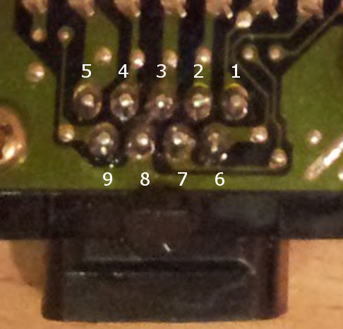
The second set of wires goes between the chip and the Player 1 controller port. Use this image as a guide:

Make sure to use the right controller port! When the logic board is flipped over, the Player 1 port is the rightmost one, while the Player 2 port is the leftmost one.
-
In the end you should be left with the pins in square brackets: these are all optional and are used to drive a LED so that it indicates the current mode, or even an LCD screen that might be useful for debugging. Please refer directly to the source code for more information about this.
-
-
Finally, test and reassemble your console! Note that you will probably have to use an RGB cable to get the new modes to display correctly on your TV. I recommend getting one from retro gaming cables: they might not be the cheapest, but they are very high quality and will give you the best possible video!