I began by seting up the DS18B20 temperature sensor with the ESP8266 shown in the TempSensor8266.ino file. After gaining comfort with the ESP8266 and how it differs from an Arduino Nano or Arduino Uno I then followed the tutorial by Random Nerd Tutorials to setup measurement recordings using Google Sheets.
Along the way I was able to combine what I knew about the temperature sensor and the above Google Sheets example and recorded temperatures. That quickly became another project for my aquarium in monitoring the temperature throughout the day. Back to the lake level project. One important thing to note was the need to connect the RST pin to GPIO 16 on the ESP8266 after programming to enable the ESP.deepSleep() cycle. This was a new thing for me and the article here goes into more depth.
I received the HC-SR04 Ultrasonic Distance sensor and took a step back. I have found that its important to not pile too much into a project at one time without any opportunity for debugging and solving unexpected problems. With that I moved back to the TempSensor8266.ino file and copied that over to a new project SonarTemp8266.ino, and made sure the sensor interface with the ESP8266 works. I followed the guide by Makerguides.com here
Learned that D2 pin does not mean pin 2, in fact it correlates to 4 in the Arduino IDE. I followed the image here. The GPIO pin number matters over the digital pin number.
Here is the datasheet for the HC-SR04 Ultrasonic Distance sensor
I encountered a problem with the baud rate or symbol rate that the ESP8266 uses for the temperature sensor is different than that of the sonar sensor. The sonar sensor operates at 9600 baud while the temperature sensor examples that I was working off of used 115200. This became quite an obstacle for me as using two separate baud rates on a single device depends on the hardware available. My solution was picking the more standard baud of 9600 as I learned the temperature sensor actually works at both rates. This solution is shown in the SonarTemp.ino.
I got the two sensors working and sending outputs that looked like this
22.13ºC
71.82ºF
Distance = 28.34 in
So awesome!
Using a tape measure and a cardboard box, I placed the box at the end of the tape measure and moved the sonar sensor along the tape measure taking note of the difference in length in the measured distance and the actual length. An adjustment of 1.17 in was added to the output distance value.
The sonar sensor had a bit of an angle to the direction of propagation. As a verification of distance measurements and their accuracy, I measured the distance from the hardwood floor, to the bottom edge of the table top, where the sensor would rest at 28.4 in. The measured distance from sensor to floor came in at 28.34 in, a 0.06 in difference I can live with.
With both major sensing components working synchronously, I moved on to outputting measurements to the Google Sheets document.
Moved Echo pin on the HC-SR04 from GPPIO pin 0 to 10, as pin 0 has to do with the FLASH function of the ESP8266 and that interfered with the uploading and flashing of new code.
To get the resource variable from Webhooks and place the resource variable in my code. Mine was something like "/trigger/lake_water_level/with/key/nAZjOphL3d-1A7gTlNSrxMJdmqy3"
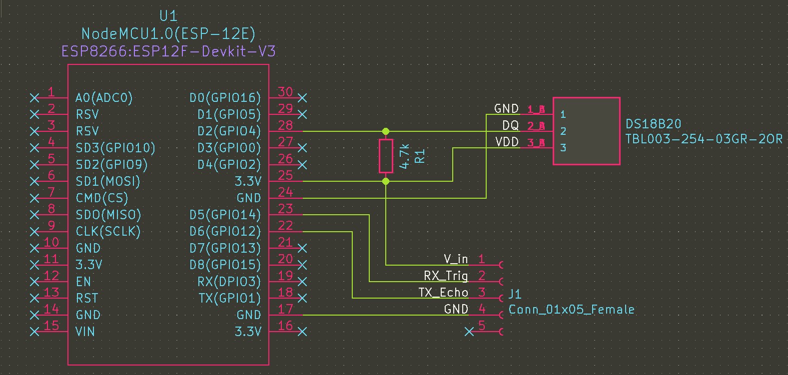
Field testing was a success, the Wi-Fi range of ~75ft worked. Had a hard time after the initial testing phase in the field with the program rebooting after power loss. I followed the ESP8266 Pinout Reference guide here and determined the pins I had connected sensors to were causing a fail in reboot. I was using GPIO0 and GPIO2 both of which cause boot to fail when pulled low due to their connection to the HC-SR04. To solve the booting issue, the Echo pin moved to GPIO12 and the Trig pin to GPIO14 as both of those GPIO ports were recommended by the ESP8266 Pinout Reference webpage. That solved the problem for me.
The example code that I was working with clocked out after five failed WiFi connection attempts. Since this project does not take into consideration the amount of power used, nor any signal interference that may be created, an infinite loop of connection to WiFi was needed.
WiFi Connection Loop Code Change
````
while(!!!client.connect(server, 80)) { // keep trying to connect to WiFi until connection is made
    Serial.print(".");
}
````
The final schematic of the data logger device.

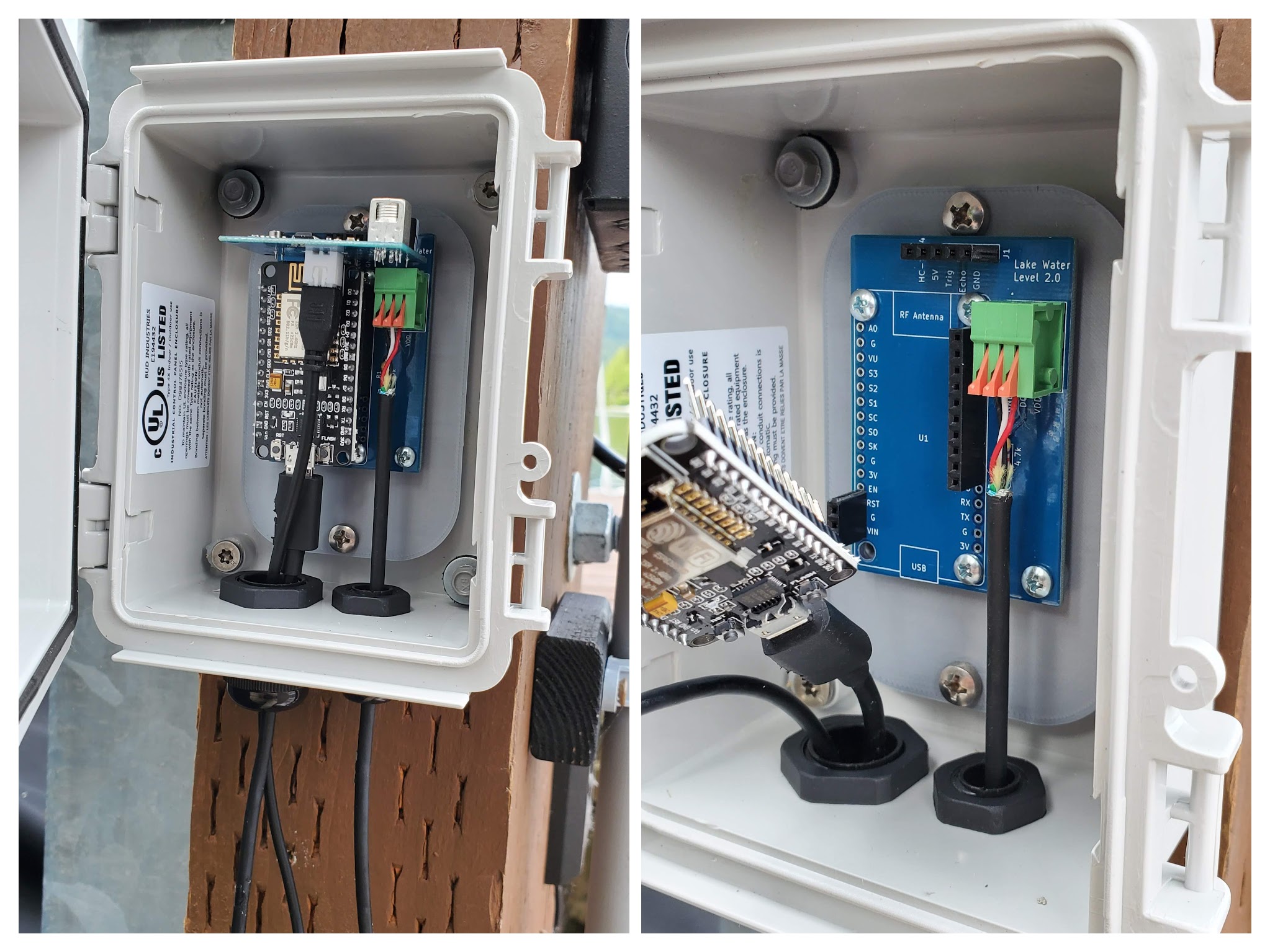
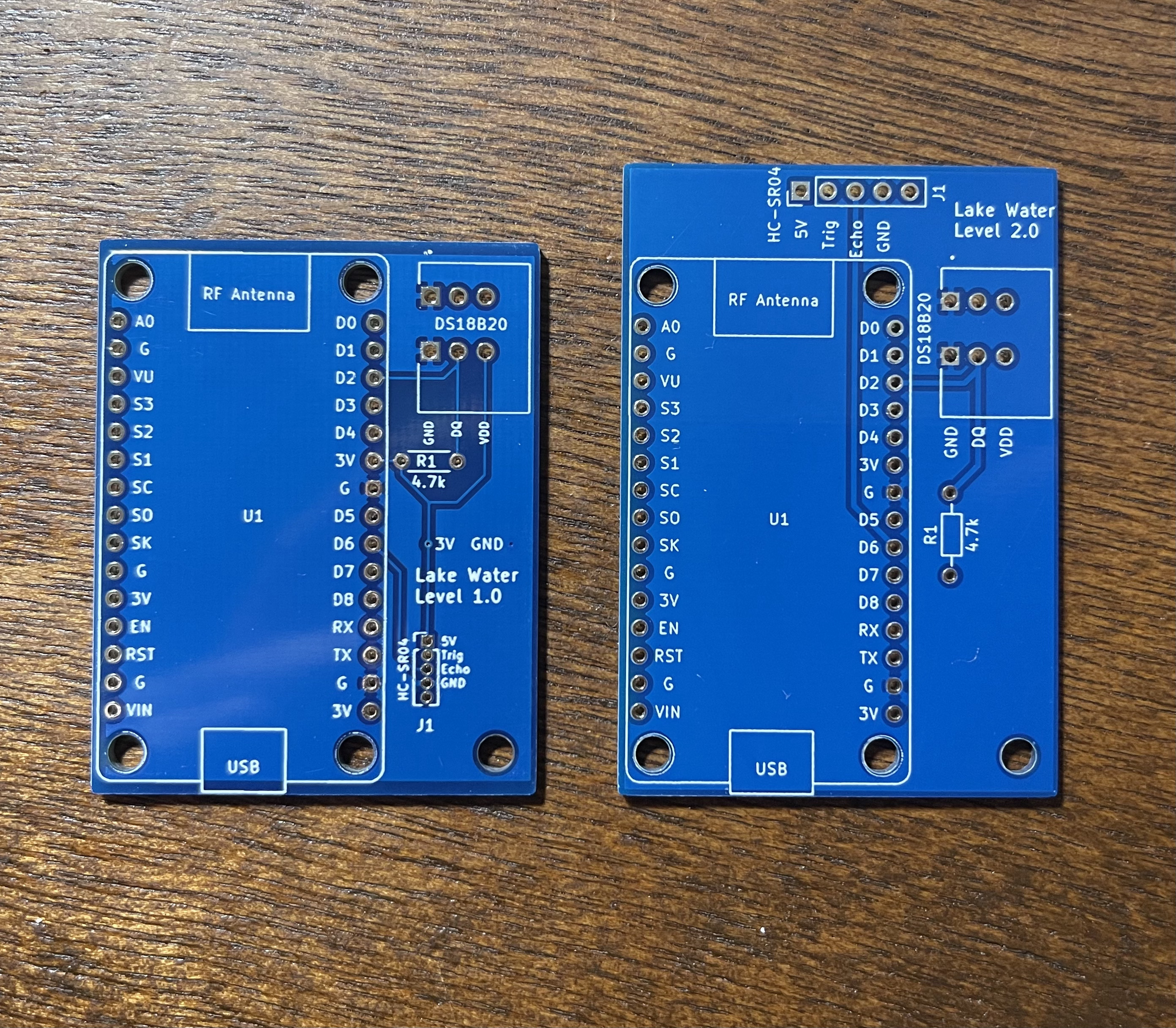
It actually took me two attempts at making a PCB, this was my first time and I did expect something like this to happen. I used the given KiCad footprints and did not discover until I was wiring up that I had picked the incorrect footprint for the female pin headers. I had 2.54mm female pin headers on hand, and the PCB holes were much smaller. Not a problem, there were a few other design changes that I wished to make and it all worked out for the best. You can see in the picture below some of the changes I made to the PCB, the smaller board was the first PCB.

