![]()
Switchless 8x Multi-Floppy-Speeder V3.3 with 512 KB RAM expansion for the Commodore C128 DCR and the internal 1571 floppy drive (DolphinDOS 3 / new DolphinDOS 25)

This project is an advanced development of the highly popular and fast DolphinDos 3 for the C128 and the 1571 floppy drive. It combines the best of the retro world with modern technology and was previously unavailable in this form. The switchless 8x Multi-Floppy-Speeder not only runs with DolphinDos 3 but also allows the operation of up to eight DOS Kernals as well as C128 and C64 Kernals, which can be conveniently activated via DOS commands. This means that, in addition to the original CBM-DOS and DolphinDos 3, JiffyDOS 128 can also be used, for example. Additionally, a TrackCache version of JiffyDOS is available, which significantly speeds up JiffyDOS. This ensures maximum compatibility.
Version 3.x now features 512 KB of RAM, compared to version 2.x, which had only 32 KB of RAM. In combination with the Peripheral Interface Adapter (PIA, type 6821 or 6521), it enables ultra-fast parallel data transfer as well as control of the 64 x 8 KB RAM banks (512 KB).
With the enhanced DolphinDos 25, the floppy drive can independently read an entire disk into the expanded 512 KB memory in two RAM pages via DOS commands and then write it back to a newly formatted disk. This process is particularly fast since no data transfer to the computer is required.
All components of the Multi-Speeder for the C128DCR are installed internally. The internal Kernal switcher synchronously switches the appropriate C128/C64 Kernal, while the internal parallel port adapter board ensures parallel data transfer. The User port remains unused externally.
The switchless 8x Multi-Floppy-Speeder with 512 KB RAM expansion for the Commodore C128DCR is one of the most versatile accelerators for the internal 1571 floppy drive of the C128DCR.
Additionally, the switchless 8x Multi-Floppy-Speeder is fully RAMBoard-compatible, allowing the use of appropriate nibble copy programs that support RAMBoard.
I have also developed this Multi-Speeder for external 1571, 1541, and 1541-II floppy drives with various matching PCBs. These can be operated in combination with each other.
- 8 x 64 KB Kernal ROM banks for C128/C64 mode
- 8 x 64 KB DOS ROM banks for the internal 1571 floppy drive
- C64/C128 and DOS Kernal can be switched (switchless) via DOS commands
- 512 KB RAM expansion for the 1571 floppy drive (64 banks, switchable via PIA)
- Parallel port for the 1571 floppy drive (PIA 6821/W65C21)
- U32 Kernal adapter socket for the C128/C64 8x Kernal switching (switchless)
- U4 6526-CIA adapter for the parallel port of the internal 1571 floppy drive
- New useful functions with DolphinDos 25
- Compatibility with RAMBoard for nibbler copy programs
A 512 KB EPROM (type 27C040 or 29F040, U3) can store up to eight Kernal operating systems for the 1571 floppy drive. A Peripheral Interface Adapter (PIA) of type 6821 or W65C21 (U4) expands the floppy drive with an additional 8-bit parallel port.
Together with the 512 KB RAM expansion (U8), it is possible to run DolphinDos 3 and my new, customized DolphinDos 25. This allows the drive to read entire tracks in a single pass, which speeds up loading programs with DolphinDos in C128 and C64 mode by a factor of 38. With DolphinDos 25 (currently in development), entire disks can be loaded into the 512 KB RAM and then written back to disks.
A microcontroller (Atmel ATMEGA328p) controls the Speeder's operating modes. It monitors the data bus of the 6502 CPU in the floppy drive and automatically switches the appropriate ROM banks as soon as a specific command (character string) is detected.
The U32 Kernal adapter for C128/C64 mode is also connected to the Speeder, allowing the microcontroller to synchronize the switching of the eight ROM banks. This means that the C128 or C64 mode Kernal corresponding to the 1571 DOS Kernal is automatically activated. The eight C128/C64 Kernals are also stored in an EPROM of type 27C040 or 29F040.
The 32 KB ROM containing the firmware for the 1571 floppy drive is normally located in the address range $8000 - $FFFF. The Multi-Speeder provides additional ROM areas for further DOS routines in the range $3000 - $3FFF. This allows the 27C040 or 29F040 EPROM of the Multi-Speeder (U3) to store custom firmware in the address ranges $x3000 - $x3FFF and $x8000 - $FFFF.
The 1571 floppy drive, like the 1541 floppy drive, has only 2 KB of working memory by default. This is extremely limited, which severely restricts the drive when reading a track. DolphinDos 3 therefore uses 8 KB of additional memory, allowing an entire track to be read into memory in a single disk rotation and then written back. This significantly increases the reading speed. Normally, the floppy drive has only a 256-byte buffer available.
The Multi-Speeder includes an AS6C4008 512 KB SRAM. This additional RAM is integrated into 64 banks within the CPU address space at $6000 - $7FFF in the 1571 floppy drive’s memory. When using a 512 KB SRAM, the 8 KB memory banks can be switched via the PIA chip in the address range $5002 - $5003 using Port PB0 to PB5. Bank 0 is activated by default.
At the end of the documentation, there is a small assembly program that demonstrates how bank switching works.
| Address | Region |
|---|---|
$0000 - $07FF |
2KB RAM (Standard) |
$1800 - $180F |
VIA 1 6522 (Serial Bus) |
$1C00 - $1C0F |
VIA 2 6522 (Drive Control) |
$2000 - $2FFF |
(Gate Array / WD 1770 / MFM) |
$3000 - $3FFF |
Expanded DOS-ROM (e.g., DolphinDos 25 routines) [^1] |
$4000 - $4FFF |
CIA 6526 |
$5000 - $5FFF |
PIA 6821/W65C21 [^1] |
$6000 - $7FFF |
SRAM 8KB / 512KB Bank 0 - 63 (64 banks) default: Bank 0 [^1] |
$8000 - $FFFF |
1571 DOS Kernal Bank [^1] |
[^1] Additionally provided by the Multi-Floppy-Speeder.
The "Switchless 8x Multi-Floppy-Speeder" for the Commodore C128DCR consists of the following components:
-
Multi-Speeder board for the socket of the 1571 CPU 6502 AD (U101)
-
Parallel port adapter board for CIA2 6526 (U4 C128) with parallel cable (optional for DolphinDos3/DolphinDos25)
-
C128/C64 Kernal Switcher board for 27256 ROM1 (U32)
_pcb_real.jpg "8x Multi-Speeder 32KB RAM Expansion Module (DolphinDos 3)")
The Multi-Speeder board is installed in place of the 6502 AD CPU (U101) of the internal 1571 floppy drive on the motherboard. The CPU is then placed into the 6502 socket (U1) on the Multi-Speeder board. However, in most cases, the CPU is directly soldered onto the C128DCR motherboard. Therefore, it must first be desoldered and replaced with a 40-pin DIP socket before the Multi-Speeder board can be installed.
The Multi-Speeder board serves as the core of the system. It provides the selected DOS Kernals for the 1571, the additional 512 KB RAM (organized into 64 x 8 KB banks), and the PIA 6821/6521 I/O chip for the parallel port. The DOS Kernals are stored in a 512 KB EPROM and organized into 8 x 64 KB banks. The ATMega microcontroller activates the desired ROM bank, which in turn enables the corresponding DOS Kernal as well as the appropriate C128/C64 Kernal via the Kernal switcher.
When a different DOS bank is activated via DOS command, the ATMega microcontroller performs a reset of the floppy drive, ensuring that the new DOS ROM with the firmware starts correctly.
The Multi-Speeder board features a (J3) connector, allowing the Multi-Speeder to be manually reset to Bank 0 (RSTROM/PIN 3) or to cycle the ROM bank by +1 (SELROM/PIN 1). The microcontroller responds when either of these pins is connected to (GND/PIN 2).
This function is particularly useful if the floppy drive crashes and no longer responds to DOS commands from the computer—for example, when an incorrect or experimental DOS ROM in the EPROM has been activated.

The Parallel Port Adapter Board is installed in place of the CIA2 6526 (U4) on the C128DCR motherboard. The CIA 6526 is then placed into the 40-pin DIP socket of the adapter.
This adapter replaces the User Port board connector, which is normally used. As a result, the User Port of the C128DCR remains free externally, and no external parallel cable is required.
The Parallel Port Adapter Board also includes a 10-pin ribbon cable, which must be connected to the Multi-Speeder board. However, this adapter board and the ribbon cable are only necessary if the 1571 floppy drive is to be operated in parallel port mode with DolphinDos 3.
In the latest version, the Parallel Port Adapter Board features only a red Micromatch connector.

The Kernal Switcher Board is an adapter board for a 512 KB EPROM (27C040 or 29F040), which contains eight 64 KB C128/C64 Kernal ROM banks. It is installed in place of the original Kernal PROM in the socket (U32) of the C128DCR.
The switcher features a connector (J3) for A16/A17/A18, which must be connected to the Multi-Speeder Board at (J5) or (J6). The Multi-Speeder Board then switches not only the floppy drive Kernal but also the corresponding bank of the C128/C64 Kernal ROM. This allows the 1571 Kernal and the C128/C64 Kernal to be switched in parallel using DOS commands, ensuring that the same ROM banks are always activated.
- If DOS Kernal bank 0 is active, then C128/C64 Kernal bank 0 is also active.
- However, the C128/C64 side does not receive an automatic reset, unlike the floppy drive, where a reset occurs automatically. A manual reset is required in this case.
If J4 on the Multi-Switcher is left open, then the floppy drive will not be reinitialized (no reset) when switching the DOS Kernal.
The Kernal Switcher V1.2 (newer version) also includes an additional fourth connection (A15) at J3, which is not used in the C128DCR.
Banks 0 - 7 can be selected using commands 1@RNROM to 8@RNROM.
The Speeder can be switched directly from the computer using simple commands. The following example demonstrates switching in C64 mode:
-
Switch to Bank 2 (JiffyDOS 64):
LOAD"3@RNROM",8,1The drive switches to Bank 2 and automatically restarts.
-
Switch to Bank 0 (DolphinDOS 3):
OPEN 1,8,15,"I:1@RNROM":CLOSE 1The microcontroller switches to Bank 0, the drive LED blinks, and the drive restarts.
-
Switch to Bank 7 (CBM DOS):
@I:8@RNROMThe microcontroller recognizes the command, switches to Bank 7, the LED blinks, and the drive restarts.
-
Temporarily Disable Switchless Mode:
@I:0@RNROM or LOAD"0@RNROM",8,1The switchless mode is temporarily disabled until the drive is restarted.
If the 1571 floppy drive is running in 2 MHz mode (C128 mode/DolphinDOS), the ROM switching may not always work reliably. The ATmega328 microcontroller may experience timing issues when reading commands from the data bus.
A more reliable operation can be achieved by replacing the Y1 quartz crystal on the board from 20 MHz to 22.1184 MHz. Although the manufacturer specifies 20 MHz as the maximum clock speed for the ATmega328P in DIP packaging, in practice, the microcontroller operates smoothly at 22 MHz.
The C128/C64 Kernal Switcher Board for the U32 socket is organized as follows. It is important to note that, for the 512 KB EPROM 27C040 and 29F040, only the upper 32 KB of the 64 KB banks from $x8000 - $xFFFF are currently used. Therefore, the Kernals must be placed starting from $x8000.
The Kernal ROM 27256 (U32) (C128/C64 Kernals) in the C128DCR is structured as follows:
| ROM Address Range | ROM Type | Size |
|---|---|---|
$0000 - $1FFF |
C64 Basic V2 $A000 - $BFFF |
8 KB |
$2000 - $3FFF |
C64 Kernal $E000 - $FFFF |
8 KB |
$4000 - $7FFF |
C128 Kernal/System | 16 KB |
The drive's Kernal ROM starts at $x3000 - $xFFFF, and depending on the active Bank (0-7), the corresponding area is mapped into the CPU address space.
| Bank | Switch | EPROM Address | CPU Address Space |
|---|---|---|---|
| 0 | 1@RNROM | $03000 - $03FFF & $08000 - $0FFFF |
$3000 - $3FFF & $8000 - $FFFF |
| 1 | 2@RNROM | $13000 - $13FFF & $18000 - $1FFFF |
$3000 - $3FFF & $8000 - $FFFF |
| 2 | 3@RNROM | $23000 - $23FFF & $28000 - $2FFFF |
$3000 - $3FFF & $8000 - $FFFF |
| 3 | 4@RNROM | $33000 - $33FFF & $38000 - $3FFFF |
$3000 - $3FFF & $8000 - $FFFF |
| 4 | 5@RNROM | $43000 - $43FFF & $48000 - $4FFFF |
$3000 - $3FFF & $8000 - $FFFF |
| 5 | 6@RNROM | $53000 - $53FFF & $58000 - $5FFFF |
$3000 - $3FFF & $8000 - $FFFF |
| 6 | 7@RNROM | $63000 - $63FFF & $68000 - $6FFFF |
$3000 - $3FFF & $8000 - $FFFF |
| 7 | 8@RNROM | $73000 - $73FFF & $78000 - $7FFFF |
$3000 - $3FFF & $8000 - $FFFF |
| Bank | Switch | System | U32 C128 | U32 C64 | U101 1571 | EPROM Address |
|---|---|---|---|---|---|---|
| 0 | 1@RNROM | CBM | CBM | CBM | CBM | $08000-$0FFFF |
| 1 | 2@RNROM | CBM RAM Exp | CBM | CBM | CBM RAM Exp. | $18000-$1FFFF |
| 2 | 3@RNROM | DolphinDos 3 | DD3 | DD3 | DD3 | $28000-$2FFFF |
| 3 | 4@RNROM | DolphinDos 25 | DD3 | DD3-Custom | DD3 | $33000 - $33FFF - $38000-$3FFFF |
| 4 | 5@RNROM | CBM-DD-SD2IEC | CBM | DD-JD-SD2IEC | CBM RAM Exp. | $48000-$4FFFF |
| 5 | 6@RNROM | CBM | CBM | JaffyDOS 1.3 | CBM RAM Exp. | $58000-$5FFFF |
| 6 | 7@RNROM | CBM (reserved JD) | CBM | CBM | CBM RAM Exp. | $68000-$6FFFF |
| 7 | 8@RNROM | CBM (reserved JD) | CBM | CBM | CBM RAM Exp. | $78000-$7FFFF |
"CBM RAM Exp." is the original CBM DOS of the 1571 with a patch for the Multi-Speeder RAM expansion. This patch includes a TrackCache, allowing the 1571 floppy drive to read an entire track at once. JiffyDOS 128 is also available in a patched version, further increasing read speed by 20%.
For more details, check out ytmytm's GitHub repository:
🔗 GitHub - ytmytm/1571-TrackCacheROM: A firmware patch for Commodore 1571 drive and internal C128D drive enabling RAM expansion use for track cache
JiffyDOS 128 runs perfectly on the Multi-Speeder. With the RAM Expansion Patch, JiffyDOS is significantly faster in both C128 and C64 modes.
📌 Note: JiffyDOS is still being sold commercially, so it is not provided for download.
- When using the Multi-Speeder board, the original DOS-ROM (U102) must be removed permanently, as the Multi-Speeder provides the selected DOS Kernal via its own EPROM.
- If U102 remains in place, it will cause an address conflict, and the floppy drive will no longer function correctly.
- ROM switching may be unreliable when the floppy drive is operating in 2 MHz mode.
- If this happens, try switching multiple times (e.g., using
LOAD"x@RNROM",8,1). - The issue is related to timing problems between the ATMega and the 74AHTC273 flip-flop under 2 MHz.
- The system works best when using a 74AHTC273.
The Peripheral Interface Adapter (PIA) controls the parallel data transfer between the floppy drive and the C128/C64, either via the Parallel Port Adapter Board or a Parallel User Port Cable.
- MC68B21P (Motorola) (2 MHz)
- W65C21N6TPG-14 or W65C21S6TPG-14 (Western Design Center)
- EF68B21 (STMicroelectronics) (2 MHz)
- R65C21P2 (Rockwell) (2 MHz)
For the Multi-Speeder DD3, I have created a RAM testing program.
- It tests RAM access and RAM bank switching.
- The tool is designed for C64 mode so that it can also be used for the C64/1541 version of the Multi-Speeder DD3.
I have created some benchmarks using the 8x Multi-Speeder V2.x.
The BOM list is available for download.
I would love to see developers contribute to unlocking the full potential of the Multi-Speeder!
Below is an assembly example demonstrating how to switch memory banks on the 1571 using the Multi-Speeder.
The memory is divided into four 8 KB banks, mapped to $6000-$7FFF in the 1571.
The banks are switched using the PIA through ports PB0 to PB5:
- PB0 = A13
- PB1 = A14
- …
By default, PB0 - PB5 are set to 0, meaning Bank 0 is active.
LDA #$00           ; PIA DDR for output ($00)
STA $5003          ; Init PIA DDR Port PB0-PB7 output direction
LDA #$FF           ; Set PIA output for Port PB0-PB7
STA $5002          ; Init PIA Port PB0-PB7 aktiv

LDA #$00
STA $5002          ; Set PIA Port PB0-PB1 low        (RAM BANK 0 active)
...
LDA #$01
STA $5002         ; Set PIA Port PB0 high / PB1 low  (RAM BANK 1 active)
...
LDA #$02
STA $5002         ; Set PIA Port PB0 low / PB1 high  (RAM BANK 2 active)
...
LDA #$03
STA $5002         ; Set PIA Port PB0 high / PB1 high (RAM BANK 3 active)`
The Atmel ATMega 328P microcontroller monitors the data bus, controls the ROM banks, and manages the switching of operating modes. The firmware can be programmed using an Arduino board or an AV programmer. I use the XGecu T48 Universal Programmer with an .mpj project file.
📌 Important: When programming with XGecu using the .mpj file, make sure not to program the EEPROM, as this may cause an error message. This option can be disabled in the XGecu menu.


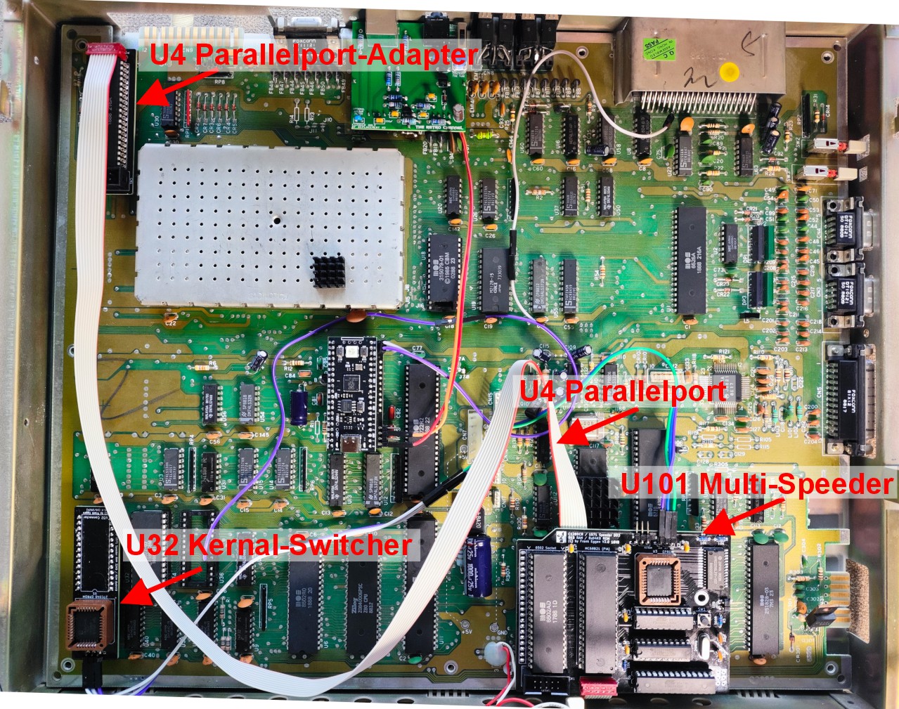
The installation of the Multi-Speeder on the C128DCR motherboard involves the following steps:
- The Multi-Speeder is installed in place of the 6502 CPU (U101).
- The 6502 CPU is placed into the CPU socket of the Multi-Speeder (bottom right).
- The Kernal Switcher is installed in place of the original Kernal ROM (U32) (bottom left).
- The Parallel Adapter is installed in place of the CIA 6526 (U4).
- The CIA 6526 is then placed into the Parallel Adapter board.
- The Kernal Switcher is connected to the Multi-Speeder board via a 3-pin cable.
- The Parallel Adapter is connected to the Multi-Speeder board via a 10-pin cable (Parallel Port).
- ATF16V8 (GAL16V8) Files
- ATMEL ATMega328 P Files
- Gerber Files for PCB Manufacturing
- Firmware / Kernals
- Schematics for the 8x Multi-Speeder
- Photo Gallery
- Additional Documents
- 8x Multi-Floppy Speeder 32KB RAM Expansion for Commodore C128DCR
- C128/C64 Kernal Switcher for 8x Multi-Floppy-Speeder C128DCR
- Parallel Port Adapter for 8x Multi-Floppy-Speeder C128DCR
- Switchless Floppy Drive 8x Multi Floppy Speeder (THT) for Commodore 1541 (V2.2c)
- Switchless Floppy Drive 8x Multi Floppy Speeder (SMD) for Commodore 1541 (V2.2c)
- Parallel Cable Sets for Commodore 1541 (SpeedDOS, DolphinDOS) with C64/C128
- DolphinDOS: C64-Wiki & Project64 Documentation
- RAMBoard: C64-Wiki & C64 Copy Protection
Many people contributed to this project, and it is the result of collaborative development. Special thanks to:
- Jan Bubela and Gunther Jilg for developing DolphinDOS.
- RetroNynjah for helping integrate his Switchless Multi-ROM into the 8x Multi-Speeder. GitHub - RetroNynjah/Switchless Multi-ROM
- Jim Drew and Joeri van Haren, for support and the review version 2.1 by Jim Drew.
- Silverdr, for his technical documentation on DD3: DolphinDOS3 Documentation
- Ytmytm, for the TrackCache ROM patch: GitHub - ytmytm/1571-TrackCacheROM
- Stefan Kauf, for support with the Multi-Speeder concept and templates.
This project has been designed and tested with great care. However, errors can always occur. Since this is a hobby project, I do not provide any guarantees for functionality or liability for damages resulting from its use.
I have spent countless hours working on this project. If you would like to support my work, you can donate to my coffee fund.
This project is free for personal use. However, commercial use, such as selling or distributing my Multi-Floppy-Speeder, is prohibited without permission.
I hope you enjoy the 8x Multi-Floppy-Speeder 32KB RAM Expansion for the C128DCR!
Best regards,
Frank Eggen
📧 retro@emden.net
- 2025-03-23 Add new Multi-Speeder Logo
- 2025-03-08 New Version 3.3 with 512KB RAM and DolphinDOS 25.
- 2025-01-02 Added more links to the 1541 8x Switchless Multi-Speeder 32KB.
- 2024-12-07 PCB Gerber file update to Version 2.0b – Fixed issues with R2 and R3. 5V must be present between pull-up resistors R2 and R3.