
The goals / steps of this project are the following:
- Compute the camera calibration matrix and distortion coefficients given a set of chessboard images.
- Apply a distortion correction to raw images.
- Use color transforms, gradients, etc., to create a thresholded binary image.
- Apply a perspective transform to rectify binary image ("birds-eye view").
- Detect lane pixels and fit to find the lane boundary.
- Determine the curvature of the lane and vehicle position with respect to center.
- Warp the detected lane boundaries back onto the original image.
- Output visual display of the lane boundaries and numerical estimation of lane curvature and vehicle position.
The complete code is available in
Advanced_Lane_Lines.ipynb
1. Briefly state how you computed the camera matrix and distortion coefficients. Provide an example of a distortion corrected calibration image.
camera = CameraModel(calibration_path = 'camera_cal/calibration*.jpg')initializes the CameraModel object with the calibration image filescamera.calibrate()This method uses the loaded images and computesmtxanddistusingcv2.calibrateCamera(). This requiresobjpointsandimgpointswhich are computed usingcv2.findChessboardCorners.mtxanddistare made into a dictionary and saved as a pickle objectcamera_calib.pkl.
camera_calib = {
               'mtx':self.mtx,
               'dist':self.dist
}camera.load_calibration()This method is then used for loading the camera_calib dictionary so that the camera need not be calibrated everysingle time the code is executed.
Following are some examples of distortion corrected images

This is shown in the previous example
2. Describe how (and identify where in your code) you used color transforms, gradients or other methods to create a thresholded binary image. Provide an example of a binary image result.
The method detect_edges(image) in LaneDetector takes care of detecting edges and returns a binary image.
First the image is converted to HSL space and L and S channels are separated. Sobel filter in x direction is applied on the L channel and scaled to get a binary image sxbinary. Gradient threshold and color thresholds are then applied on scaled binary image sxbinary and color binary image color_binary and then stacked together to form a combined image combined_binary.

3. Describe how (and identify where in your code) you performed a perspective transform and provide an example of a transformed image.
Perspective transform is handled by the CameraModel class.
transformed_img_1,M_inv_1 = camera.perspective_transform(distorted_image_1)
This returns the transformed image with the inverse transformation matrix for this particular image which is useful to again get back the original transform.
The source and destination points are defined as follows
src = np.float32([[w // 2 - offset, h* 0.7],
                  [w // 2 + offset, h * 0.7],
                  [offset, h],
                  [w - offset, h]])

dst = np.float32([[offset, 0],
                  [w - offset, 0],
                  [offset, h],
                  [w - offset, h]])
These src and dst points are used to compute perspective transform and subsequently warp and unwarp the image.
M = cv2.getPerspectiveTransform(src, dst)
warped = cv2.warpPerspective(image, M, img_size, flags=cv2.INTER_CUBIC)

M_inv = cv2.getPerspectiveTransform(dst, src)
I verified that my perspective transform was working as expected by drawing the src and dst points onto a test image and its warped counterpart to verify that the lines appear parallel in the warped image.


4. Describe how (and identify where in your code) you identified lane-line pixels and fit their positions with a polynomial?
I used the sliding window approach to compute the first set of curves and then just used the previous curve parameters to detect new curves.
get_lanes uses multiple windows along y axis defined by LaneDetector.n_windows and uses sliding window approach to find the lane points. numpy.polyfit is the used to find the curve parameters left_fit,right_fit.
(left_fit,right_fit, ploty),road_attributes,_ = LaneDetector.get_lanes(binary_warped)get_lanes_without_window_search uses the left_fit,right_fit from the previous detected curves and computes new curve params by looking around the old curve
(left_fit,right_fit, ploty),road_attributes,_ = LaneDetector.get_lanes_without_window_search(binary_warped)Finally get_road is used to return an unwarped final image with lane drawn over it.

5. Describe how (and identify where in your code) you calculated the radius of curvature of the lane and the position of the vehicle with respect to center.
We know the equation of curve is defined by:

and we computed the lane parameters left_fit,right_fit which gives A_left,B_left,C_left and A_right,B_right,C_right respectively.
The real world scaling factors are defined as:
ym_per_pix = 30/720
xm_per_pix = 3.7/700
considering maximum y-coordinate, we the radius is computed by the following formula

Its is calculated by
car_position = self.xm_per_pix*width/2
road_center = (true_left_x + true_right_x)/2
dist_from_center = road_center - car_position
where true_left_x , true_right are real world x- measurements at maximum y.
The complute lane attributes are stored as a dictionary
road_attributes = {
					'radius_of_curvature':(left_curverad+right_curverad)/2.0,
                    'dist_from_center':dist_from_center
                  }
6. Provide an example image of your result plotted back down onto the road such that the lane area is identified clearly.
The get_road method from LaneDetector class returns final image with lanes draw over it and annotated with lane attributes such as lane curvature and distance from center

1. Provide a link to your final video output. Your pipeline should perform reasonably well on the entire project video (wobbly lines are ok but no catastrophic failures that would cause the car to drive off the road!).
The class initializes models necessary for this project and loads the camera calibration
def __init__(self,calibrate=False):
    self.camera = CameraModel(calibration_path = 'camera_cal/calibration*.jpg')
    if calibrate == True:
        self.camera.calibrate()
    self.camera.load_calibration()
    self.ld = LaneDetector()
The complete pipeline is given below
def detect_lane_lines(self,image):
    undist_img = self.camera.undistort(image)
    edge_image = self.ld.detect_edges(undist_img)
    final_result,M_inv_final = self.camera.perspective_transform(edge_image)
    final_image = self.ld.get_road(final_result,M_inv_final,undist_img)
    return final_image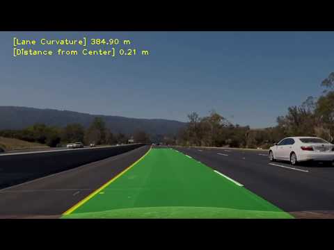
1. Briefly discuss any problems / issues you faced in your implementation of this project. Where will your pipeline likely fail? What could you do to make it more robust?
The primary problem which I faced in this implementation was the outliers which caused the curve to go haywire when the lighting changes in the image. To make the curve generation smoother, I implemented a moving average filter with a buffer size of 20 code snippet is shown below. The left curve and right curve parameters are considered as 3x1 vectors and passed to individual moving average filters. To add to it, I use the previous curve parameters and use weighted addition to the new parameters.
new_params = gamma x previous_params + (1 - gamma) x new_params
def moving_average_filter(self,left_fit,right_fit):

        left_curve_params = np.array([left_fit])
        right_curve_params = np.array([right_fit])

        #-----------------------------------------------------------#
        if self.left_buffer.size == 0:
            self.left_buffer = left_curve_params
            left_vect = np.mean(self.left_buffer,axis=0)
        else:
            previous_left = self.left_buffer[-1]
            self.left_buffer = np.concatenate((self.left_buffer, left_curve_params), axis=0)
            left_vect = (1-self.gamma)*np.mean(self.left_buffer,axis=0) + self.gamma*previous_left

        if self.left_buffer.shape[0] > self.BUFFER_SIZE:
            np.delete(self.left_buffer,0,axis=0)
        #-----------------------------------------------------------#
        if self.right_buffer.size == 0:
            self.right_buffer = right_curve_params
            right_vect = np.mean(self.right_buffer,axis=0)
        else:
            previous_right = self.right_buffer[-1]
            self.right_buffer = np.concatenate((self.right_buffer, right_curve_params), axis=0)
            right_vect = (1-self.gamma)*np.mean(self.right_buffer,axis=0) + self.gamma*previous_right

        if self.right_buffer.shape[0] > self.BUFFER_SIZE:
            np.delete(self.right_buffer,0,axis=0)

        return left_vect ,right_vect